
Das Anleitung des Scott Stereomaster 380 ist sehr selten

Hier sehen sie die englische Originalversíon aus dem Jahr 1963, als zur Funkausstellung Berlin 1963 bei uns die ersten echten funktionierenden Stereo-Receiver vorgestellt wurden. Einen davon hatten wir von Professor Hergesell und Professor Schwarze gespendet bekommen - bereits in 2014. Und jetzt in 2024 ist das "user manual" in den großen Stapeln von Dokumenten aufgetaucht.

Vorab-Bemerkungen zu diesem 1963er Handbuch - genannt "Operating Manual"
Wir schreiben das Jahr 1963 und die Ingenieure, die - nicht nur bei Scott - diese Geräte entwickelt hatten, und nur sie, die wußten ziemlich genau, was machbar war und was nicht und wo eventuelle Probleme auftauchen könnten.
Und es gab damals keine PC-Technik oder Schreibautomaten. Alles mußte erstmal getippt - natürlich möglichst schnell / in time - und dann in der Setzerei (oft in der Druckerei) in Proportionalschrift im Bleisatz gesetzt werden. Dann wurden die Bilder und/oder die Zeichnungen und Grafiken an die entsprechenden Stellen eingeklebt und dann erst konnte gedruckt werden.
Solch ein Handbuch ist darum schon ein kleines Wunderwerk, über das wir heute in 2024 mit Pagemaker oder Word nur lächeln können. Damals war das ein großes Werk. Ohne Manual durfte auch in den USA kein Gerät die Fabrikation verlassen.
Der H.H. SCOTT Stereomaster 380 war 1963 das Spitzengerät

Ich betone das immer wieder, weil es bei Scott noch 5 andere deutlich leistungsschwächere Receiver gab. In 1963 waren die 2 x 35 Watt Sinus-Leistung an allen Imperdanzen eine Wucht. Auch die UKW Emfangsqualität in Stereo war erstaunlich hoch angesiedelt. Da mußten sich die deutschen Wettbewerber ganz schön anstrengen, zumal sie zur Funkausstellung mit ihren Stereo-Decodern noch gar nicht fertig waren. Die Story steht auf den Seiten vom ersten Stereo in Deutschland.
.
SCOTT STEREO TUNER/AMPLIFIER Stereomaster 380

LOOK HOW EASY IT IS TO OPERATE YOUR 380, STEREO TUNER-AMPLIFIER
.
This simplified photo-guide shows how to use your new tuner-amplifier. A similar guide on the inside back cover shows how to connect the tuner-amplifier to the rest of your music system.
However, we strongly suggest that you read the complete instruction book thoroughly. Only then will you get the utmost enjoyment and maximum performance from this superb instrument.
.
TUNING METER

For best listening adjust the tuning dial so that you get the highest possible reading on the meter, (see pages 18 and 5)
.
INDICATOR LIGHTS
Light up to indicate signal source, such as Phono, FM, etc. (see page 12)
.
STEREO INDICATOR
Goes on when tuned to a stereo broadcast.
TUNING KNOB
To select the desired FM station, (see page 18)
.
INPUT

> Phono - for phonograph records.
> FM Mono - To receive FM monophonic broadcasts. Automatic Stereo - Use this position most of the time. The tuner will automatically switch to stereo if you are tuned to a stereo broadcast (a light will indicate this). If the program is monophonic, the tuner will instantly switch to that mode of operation. The tuner does all the thinking for you.
> Stereo - Sub. Ch. Filter - To receive FM stereo broadcasts when some background noise is present.
> AM - To receive AM broadcasts.
> Extra - For any device connected to the extra inputs on back, (see page 12)
.
EQUALIZATION
RIAA - to listen to phonograph records, (see page -2) NAB -to listen to a tape deck, (see page 13)
.
RUMBLE
To reduce low frequency noises such as turntable rumble, (see page 16)
.
Monitor
To listen to tape played on a regular Tape Recorder, (see page 16) - This switch can also be used to monitor a recording when used with a tape recorder with separate playback and record heads, (see page 16)
.
SELECTOR

For all stereophonic program material, set to Stereo position. Other positions are for monophonic material, or for balancing the system, (see page 14 and 13)
.
BASS
Modifies low frequency sounds. Set to suit your taste, (see page -5)
.
LOW LEVEL OUTPUT
To connect a set of low impedance stereo headphones, (see page 8)
TREBLE
Modifies high frequency /sounds. Set to suit your taste. (see page 15)
.
BALANCE
To make one speaker louder than the other. Permits you to adjust for unequal sounds caused by room acoustics or faulty program material, (see page 14)
.
POWER
To turn the tuner-amplifier on or off. Will also supply power to any device connected to switched AC outlet on the back. (see page 11)
LOUDNESS
Makes system louder or softer to suit your taste (see page 14)
.
COMP
In "Loud." position introduces a circuit that boosts the extreme high notes and low notes for listening at low levels, and is out of operation automatically at loud levels. "Vol." position removes circuit completely, (see page 14)
BANDWIDTH
Wide - for good program material or strong, local AM stations, (see page 16)
Distant - for noisy program material or distant AM stations, (see page 19)
.
SPEAKERS
You can turn off the speakers if you want to use your headphones and not disturb others, (see page 17)
INTRODUCTION
- Mono war noch lange nicht "out" darum hier beide Varianten

Your new tuner-amplifier represents a significant breakthrough in the design of quality music reproducing equipment for the home. Frequently manufacturers have been forced to sacrifice some part of the best possible performance in order to combine a stereo tuner and stereo amplifier on one chassis. There is no compromise in your new Scott tuner-amplifier. The remarkable design and unique features that make separate Scott tuners and amplifiers outstanding are fully represented in this combination unit.
In the next few sections you will read about Scott leadership in both amplifiers and tuners. The sum of this leadership is the Scott tuner-amplifier; representing the ultimate in performance, appearance, and operating convenience. We are sure you will find this background material of interest.
Although your tuner-amplifier is a simple instrument for any member of the family to operate, to obtain the maximum enjoyment read this entire instruction booklet carefully and thoroughly. You will find it well worth the time.
.
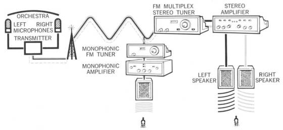
HOW FM STEREO (MULTIPLEX) WORKS

Multiplexing is a method of broadcasting two or more signals from one FM transmitter. This means that a single FM station can broadcast both the left and right channels of a stereophonic program from records, tapes, or live performances.
Humans are capable of hearing sounds between about 20 and 20,000 cycles per second. Any sound above 20,000 cycles per second is referred to as "supersonic" because it is above the range of human hearing.
Most good FM tuners are capable of reproducing these supersonic frequencies above 20,000 cycles per second ("cps" for short). Though you cannot hear them, these supersonic frequencies are used very effectively for multiplex. At a frequency of 38,000 cycles per second (cps), high above the sounds you can hear, the second (stereo information) signal is added on. While you can't hear this second signal, your FM tuner can, and, if equipped for multiplex, will convert this into sound you can hear - stereo sound.
This second signal is not either the left or right channel. If it were, a listener with a monophonic tuner would hear only half of the program. Instead (see diagram below), a method is used that provides the full monophonic signal (left plus right) for the listener with a regular FM tuner, and stereo for the listener with multiplex equipment. The stereo quality depends on how well the multiplex tuner handles the second signal (stereo information). If very little of the second signal is being properly processed, there will be poor stereo quality (poor separation between the left and right channels). Simply having sound from both speakers does not necessarily mean you have stereo.
Conventional narrow-band tuners cannot give the fine stereo quality obtained with Scott Wide-Band tuners. As the FCC pointed out, the approved multiplex stereo system "... like any multiplex transmission system, will increase energy transmission at the edges of the channel involved. Accordingly for optimum stereophonic reception, the (tuner's) bandwidth ... must be considerably greater than that of monophonic (tuners) .... "
*Scott tuners have always had the wider IF bandwidth needed.
Since stereo FM broadcasts are such an abundant source of high quality program material, many listeners will want to make off-the-air stereo tape recordings. In many instances, however, conventional multiplex circuitry causes interference with a tape recorder, resulting in whistles and beeps being recorded on the tape. Scott multiplex units incorporate the expensive filters needed to prevent this interference. Scott equipment can be used with any tape recorder.
New FM Stereo will bring you thrilling broadcasts of world famous symphony orchestras and opera companies ... intimate close-ups of jazz in stereo ... dramatic presentations with life-like movement. You will hear the wonderful new sound of FM multiplex stereo in your home ... and using Scott equipment, you will be able to make flawless off-the-air stereo tape recordings.
*See paragraph 36, FCC Report and Order, Docket No. -3506,^/-9/6-.
.
HERE'S WHAT MAKES SCOTT TUNERS SO OUTSTANDING

FM stereo multiplex reception makes more severe demands on a tuner than regular monophonic reception. You will undoubtedly enjoy your new Scott tuner much more if you have some understanding of the unique engineering that makes these tuners so outstanding. Below are some of the various factors that go into the design of a Scott tuner.
Usable sensitivity - indicates a tuner's ability to receive weak signals with very low hum, noise and distortion. Scott's high usable sensitivity is in part due to the silver- or copper-plated front end on Scott tuners. The high conductivity of these metals preserves the full quality of even the weakest signals without introducing the noise, hum or distortion of conventional tuners.
.
- Anmerkung : Das mit dem "outstanding" (besonders herausragend) war solch ein typisch amerikanischer Werbespruch, der bei fast allen Geräten irgendwo zu lesen stand, sogar bei billigsten 100 Dollar Komplettanlagen mit Plattenspieler, Kassettengerät und 2 Boxen. Alles in den USA war "outstanding". Manchmal stimmte es sogar - wie hier beim 380.
.

Instead of inexpensive steel chassis, Scott uses electrolytic aluminum with copper cladding in the critical IF and multiplex sections. Copper is a far better conductor than steel and eliminates the losses ordinarily associated with that metal. Aluminum, being non-magnetic, tends to reduce hum and noise, giving Scott tuners an exceptionally high signal-to-noise ratio.
Selectivity - is the ability to completely separate stations on nearby channels. Scott's Wide-Band IF's most closely approach the ideal by amplifying the desired signal and completely rejecting all nearby stations. Scott tuners separate stations that conventional narrow-band tuners would pass by.
.

Freedom from drift - a tuner must stay on station without wandering (or drifting). Narrow-band tuners use undesirable automatic frequency control (AFC) to prevent drifting. AFC introduces considerable distortion and reduces bass response. AFC also reduces selectivity because its magneticlike attraction towards stronger stations pulls away from nearby weak ones. Scott tuners utilize Wide-Band design rather than AFC to eliminate drift, bringing you the full range broadcast without introducing distortion.
Stereo separation with low distortion - a must for good FM stereo reception. Conventional narrow-band tuners inherently cannot give as fine stereo quality as Wide-Band tuners. Scott-developed, Time Switching Multiplex circuitry provides full frequency response with extremely low distortion. Stereo separation far exceeds specifications established by the Federal Communications Commission.
.
HERE'S WHAT MAKES SCOTT AMPLIFIERS SO OUTSTANDING
The first true high fidelity amplifier was Scott's world famous 210A which appeared in 1947. This remarkable instrument introduced a score of unusual design features which today are accepted and used by all manufacturers.
The engineering innovations in the 210A are typical of H. H. Scott, a company which has continued to pioneer in the audio field. The exceptional design and careful manufacture that went into the 210A have been proven over the years ... most are still in service,-- working perfectly.
Scott's philosophy is not only to develop new and better instruments, but also to produce equipment that will last. There is no built-in obsolescence in Scott products. Here are a few of the "extras" Scott has included in your new tuner-amplifier:
• Non-magnetic electrolytic aluminum is used as chassis material on all Scott components rather than low cost steel. Aluminum acts as a shield against induced hum, and is an ideal heat dissipator guaranteeing long life and cool operation of the vital output stages.
• To avoid unpleasant hum and noise, Scott uses specially selected preamplifier tubes.
• All Scott amplifier sections are 100% stable with any type of load or with no load. You never have to worry about harming your tuner-amplifier if a speaker wire is disconnected.
• The oversized output transformers in all Scott amplifier sections mean that you will get plenty of output power at the low frequencies where power is really needed. Any amplifier can meet its rated specifications in the midrange. It is in the vital low frequency region that Scott stands out as the leader.
• All Scott amplifier sections incorporate a subsonic sharp cutoff filter. This prevents all noise and rumble below 20 cps from entering the amplifier stage and causing the amplifier to waste its power on undesirable noises. By concentrating on the audible range, a
Scott amplifier gives usable power far in excess of its conservative rating.
• All components and parts are carefully checked. They are used far below their rated values. You can be sure that your new Scott tuner-amplifier will meet its specifications, both now and for years to come.
.
INSTALLATION

Your Scott tuner-amplifier can be placed on a table or bookshelf, in existing furniture like an end-table, buffet, or room divider, or in a specially designed equipment cabinet. A handsome hand rubbed wood accessory case is available from your dealer in finishes to blend with vour decor.
Wherever it is placed, adequate provision should be made for ventilation. If this is not done, the life of the internal components will be appreciably shortened. By adequate ventilation we mean about 4" of space above and behind the unit where air may circulate freely, or, if it is installed in a cabinet, the cabinet should have an open back.
To help disperse heat rapidly, Scott employs aluminum in the construction of the chassis and panel. Aluminum is an excellent conductor of heat. Therefore, the panel may seem warm to the touch. As long as the unit is adequately ventilated, this is of no consequence.
The tuner-amplifier should always be mounted horizontally because of the necessity for proper heat dissipation. If vertical mounting is desired, forced air ventilation with a fan is a must. Fans specially designed for this purpose can be obtained from your dealer.
.
CONNECTIONS TO A STEREO SPEAKER SYSTEM

Terminal strips for speaker connections are located on the rear of your tuner-amplifier. The screws marked Right are for connecting the right-hand speaker (as you face them from your listening area), the ones marked Left are for the left hand speaker.
Every speaker is rated by its manufacturer at a certain impedance. This information is either marked on the speaker or can be supplied by your dealer. You will note that there are screws marked 4, 8, and 16 (Ohms) on the terminal strips. These numbers indicate the correct connection to the loudspeaker, and permit you to match the output of your amplifier to the impedance of the speaker.
When making connections, you can use almost any type of wire if the lengths are under 50 feet. We highly recommend ordinary lamp wire (#22 wire according to the electrical code). If you want to run the wire under a rug you can also use flat TV antenna wire. If you plan to use wire lengths considerably in excess of 50 feet, it is advisable to use #18 wire to prevent excessive losses of power.
When attaching the wire to the tuner-amplifier or the speaker be certain that strands of wire from one screw do not accidentally touch strands on any other screw or the speaker will not perform properly. After the speakers are connected they should be properly phased to give a well-spread stereo effect with full bass. Phasing instructions are to be found at the back of this manual.
.

Your tuner-amplifier includes two terminal strips on the rear. The upper strip is designed solely for setting the unit to match the impedance of your speaker. Connect the cables with the spade lugs on the end to the terminal screw (either 4, 8, or 16) that most closely coincides with the rated impedance of your speaker. One cable and set of screws are for the right speaker and one for the left speaker. By having two sets, you can match impedances properly even if you are using speakers with different impedances.
The bottom terminal strip is for connecting the speaker wire. Connect one end of the speaker wire to the two terminals on your left hand speaker or speaker enclosure. Connect the other end to the "0" and "H" terminals for the left channel. Repeat for the right hand speaker.
If you only own one speaker system and plan to add a second speaker for stereo at a later date treat the single speaker as a left channel speaker and operate the amplifier with the Selector in the Bal L. position at all times. It is not safe to operate conventional amplifiers without a speaker load.
However, all Scott amplifier sections are completely stable with resistive, capacitative, inductive, or no load. You need never fear injury to your tuner-amplifier by using it with no load on the right channel. Do not attempt to parallel the outputs. Such a procedure may reduce the power output and increase the distortion.
.
CONNECTIONS TO THE FM ANTENNA

An FM dipole antenna is supplied with the unit. In strong signal areas this should be more than adequate to pull in most of the FM stations available. Antenna connections are made to the terminal strip marked "Antenna" located on the back panel.
The dipole leads are connected to the screws marked "G" and "FM-300 ohms" respectively as shown. The dipole should then be opened to full "T" and positioned to give the strongest signal possible on the meter on the front. The meter shows a strong signal when the pointer is at its highest reading.
The dipole may have to be shifted slightly when trying to receive stations at different directions from the listener. A compromise position can usually be found that will work best for most of the stations desired.
Generally, the higher the dipole can be placed, the stronger the signal. If you wish to place the dipole further away than its present lead length permits, you can purchase from your dealer additional lengths of 300 ohm antenna wire to connect between the dipole and the antenna terminals.
.

In fringe areas, or areas of high interference, an external directional antenna may be necessary. This is particularly true with multiplex stereo reception. Reflections from hills or nearby tall buildings can cause annoying distortion.
There are many fine yagi FM antennas available which will provide strong signal and reduce provide strong signal and reduce interference, thus enhancing the range of the tuner. The remarkable sensitivity of your Scott tuner-amplifier, when combined with a good anttnna, will permit you to receive an astonishing number of distant FM stations, either monophonically or in stereo.
In areas of extremely high noise, such as a busy highway, the following system is suggested:
Mount a yagi antenna (either single or stacked) at some point as far removed from the source of the disturbance as possible. Connect a 300 ohm to 72 ohm transformer on the mast, and run 72 ohm shielded antenna lead-in wire to the tuner-amplifier. The lead-in should not be more than 50 feet in length, if possible. Since the yagi antenna is extremely directional, it is important that it be positioned for the best reception of desired stations. In areas where stations are available in diverse directions, an antenna rotator is suggested.
.
CONNECTIONS TO A CENTER CHANNEL SPEAKER OR MONOPHONIC EXTENSION SPEAKERS
One of the many exclusive stereo features pioneered by H. H. Scott is the derived third (or center) channel. This extra output is used in conjunction with an auxiliary amplifier to fulfill several important needs:
.
- 1. It gives fuller sound, particularly in large rooms where it is necessary to separate speakers by more than eight feet.
- 2. It allows ideal seating for full stereo in a much greater portion of your listening room giving you greater freedom in placement of speakers and furniture.
- 3. It lets you feed a full monophonic signal to single extension speaker systems in other rooms like kitchen, den, porch, bedroom or bath. With an ordinary two channel system you feed just half the signal to an extension speaker.
.
Derived Center Channel Preamp Output Jack

Connect a shielded audio cable from the Derived Center Channel Output jack (labeled "Der. Ctr. Ch.") on the back of your Scott tuner-amplifier to the input of a separate power amplifier. Use the 1.5 volt input if it is an H. H. Scott power amplifier and a high level input (such as tuner, extra, etc.) on any complete amplifiers. Set the level control so that the center channel loudspeaker's sound is lower in volume as compared with the left and right stereophonic speakers.
If the center channel is driving extension speakers, the separate loudspeakers can be equalized by using individual "T" pads on each speaker. A "T" pad is a specially designed level control that is readily available from your dealer.
The center channel output is controlled by all the front panel controls, therefore, the auxiliary amplifier should have a volume or level control to be able to obtain the proper balance. It is essential that the center channel speaker be in phase with the right and left channel speakers for proper operation. See section on phasing found later in the manual.
.
Powered Center Channel Output

In addition to the derived center channel output described above, a powered center channel output capable of directly driving center channel or extension speakers without a separate power amplifier is provided. Connect one end of the speaker wire to the two terminals on the back of the speaker system. Connect the other end to the "0" and "H" terminals under Center Channel (on the same strip that you connected the right and left speakers). If this output is to be used as a center channel, then the speaker should be in phase with the right and left speakers. Phasing instructions will be found in the back of the manual.
Using the derived center channel preamp output described in the previous section provides greater flexibility, depending on the power of the separate amplifier. If many extension speakers are desired, this method is preferable. However, for most normal requirements, the powered center channel output is certainly adequate and more convenient in that a separate amplifier is not needed.
.
LOW LEVEL STEREO OUTPUT JACK

A low level, low impedance output jack is located on the front panel. This jack will accept the standard three-conductor phone plugs found on most popular low impedance stereo headphones. When using this jack, make sure that the plug is pushed in firmly.
When the headphone plug is inserted in the front panel Low Level Output jack, the Speakers switch on the front panel can be switched to OFF position. This will completely cut off sound from the loudspeakers, permitting use of the Low Level Output jack. This allows you to monitor tape recordings without any sound from the loudspeaker systems; absolutely necessary when recording from a microphone. If desired, the speakers and the Low Level Output jack may be used simultaneously.
.
CONNECTING TO LOW LEVEL INPUTS
Stereo Record Player with Magnetic Cartridge
Magnetic cartridges are generally considered the best for faithful reproduction of the sound in the record groove. However, their electrical output is very small, on the order of a few millivolts (thousandths of a volt).
The output is so small that your amplifier incorporates a special circuit known as a preamplifier section, specially designed to give this tiny signal a large boost before it goes into the regular power amplifier section.
.

There is a wide variation in output from one make and model of magnetic cartridge to another. Some cartridges produce outputs as low as 3 millivolts while others are over 12 millivolts. If the preamplifier is designed to amplify only a 3 millivolt signal, a 12 millivolt cartridge will overload the amplifier and create too much volume (at higher distortion).
On the other hand, using a 3 millivolt cartridge with an input designed for 12, will not provide adequate listening volume.
Scott engineers have solved this problem by designing two different sets of inputs - one designed for low output magnetic cartridges and one designed for high output magnetic cartridges. If your cartridge has an output of 6 millivolts or less, use the Mag Low inputs. If it has an output of 7 millivolts or higher, use Mag High. Most cartridges will be used in the Mag High inputs.
Information on cartridge output is undoubtedly listed in the literature that came with it. If it is not, your dealer can supply the needed information.
To connect a turntable or changer utilizing a magnetic stereo cartridge, connect the shielded leads from the player to the Magnetic inputs on the back of the amplifier. Check the instructions provided by the record player manufacturer to be certain that you are inserting the left channel lead into the left input of the amplifier and the right input into the right channel.*
* Use either Mag High or Low. Do not use both Mag High and Low at the same time.
.
Stereo Record Player with Ceramic or Crystal Cartridge
A ceramic or crystal cartridge differs from a magnetic cartridge in the amount of output generated. Whereas a magnetic cartridge produces a signal of a few thousandths of a volt, a ceramic or crystal cartridge is capable of outputs of at least one half volt. (340 and 380 series)
When using a ceramic or crystal cartridge, the inputs marked Ceramic on the rear of the amplifier should be used. The lead carrying the left channel information should be connected to the Left Channel Ceramic input; the lead carrying the right channel information should be connected to the Right Channel Ceramic input.
Either the ceramic or magnetic high and low inputs may be used; not all three at the same time. In other words, if you are using a ceramic cartridge connected to the Ceramic inputs, neither Magnetic High or Magnetic Low may be used.
(LR-40 series) Connect to the Extra Input on the back of the tuner-amplifier.
.
Monophonic Record Player
The instructions outlined above are equally valid here. The only difference is that there will be only one lead to connect and this should be inserted in the Left input. To play a monophonic record so it is heard over both loudspeakers, turn the Selector switch to L. Input.
.
Stereo Tape Deck (380 Series)

A tape deck is a machine without playback preamplifiers. The
signal is fed directly from the tape heads without any additional amplification. A very small electrical signal is produced similar to that obtained from a magnetic phonograph cartridge. With your Scott tuner-amplifier you can connect both a tape deck and a record player, and select either from the front panel.
Connect the leads to the Tape Head input on the back panel. To listen to tape, move the Equalization switch to the NAB tape position. This will switch the input from phono to tape head. The Input switch must be in the Phono position in order to listen to either the tape head or record player.
.
GROUNDING YOUR RECORD PLAYER OR TAPE DECK
Many turntables, changers, and tape decks must be grounded to reduce hum to unobjectionable levels. A copper colored screw will be found on the top rear of your tuner-amplifier. A few turns with a screwdriver will loosen it. Connect any grounding wires to this screw, and then tighten. Carefully read all the instructions provided with your cartridge, record player, or tape deck relating to hum reduction. If unusual problems present themselves write to the address given at the back of this manual.
EXTRA INPUT

An extra stereo input is provided for any other high level source
you may wish to connect. You can connect a second tape recorder, ceramic microphone, or sound from your TV set. If this extra source is a stereophonic device with two leads, connect the left channel lead to the left channel Extra input and the other to the right channel Extra input. Set the Input switch to Extra. If it is a monophonic device with only one lead, connect it to the left channel Extra input. To listen to this latter signal over both speakers you should turn the Selector switch to L. Input position and the Input to the Extra position.
CONNECTING YOUR TAPE RECORDER
To Make Tape Recordings

Your Scott tuner-amplifier has a special set of outputs which permit you to record any signal passing through the unit. You can make tapes from your records or off-the-air from FM. The tape recorder output is completely unaffected by the volume and tone controls of the tuner-amplifier. If you want to turn the volume down to "0", you can and it will not affect the output to the tape recorder. Connect an audio cable from the left channel Recorder Output on the tuner-amplifier to the left input of the tape recorder. Repeat for the right channel.
Some tape recorders have both a high level (or tuner) input and a low level (or microphone) input. Use the high level input for all connections from the tuner-amplifier. If there is any question, refer to the recorder instructions and follow accordingly. If you have a monophonic tape recorder, connect the left channel Recorder Output to the tape recorder.
To Playback Tape

If your stereo tape recorder has its own playback preamplifier, connect an audio cable from the left channel output to the left channel Recorder Input jack on your tuner-amplifier. Repeat for the right channel. In order to listen to the tapes, slide the tape Monitor switch on the front panel to the IN position. When the tape Monitor switch is in this position, it completely bypasses the Input switch and permits you to hear the tapes regardless of the position of that switch.
When you are finished listening to the tapes, immediately return the tape Monitor switch to the OUT position so that the Input switch becomes operative again.
If you are listening to a monophonic tape recorder connect the tape recorder's output cable to the left channel Recorder Input jack. Use the tape Monitor switch as described above, but in addition, turn the Selector switch to L. Input so that the sound can be heard over both speakers.
If your tape recorder has a separate record and playback head, it may be possible to monitor the tape while you are making a recording. This will be described in the section on MONITOR.
.
POWER (das sind USA / 110V Buchsen - bei uns 230V))

The power cord should be plugged into any 105 to 125 volt, 50 or 60 cycle AC source (wall outlet). Do not attempt to use with a DC outlet.
There are two accessory AC outlets on the rear panel. One of the outlets is controlled by the front panel On-Off Switch and is colored black. Your tuner, tape deck or recorder may be plugged into this outlet. When you turn off your amplifier anything plugged into this outlet will automatically be turned off as well.
The second accessory AC outlet (colored red) remains "live" as long as the amplifier itself is plugged in. It is suggested that your record player be connected to this outlet. This will insure that no rumble-producing "flat spot" will occur in your record player if you turn the amplifier off before the record player has completed its cycle. When this output is used you must independently shut off the device plugged into it.
.
HOW TO USE YOUR TUNER-AMPLIFIER
.
AMPLIFIER SECTION
Your new Scott tuner-amplifier has a wide variety of controls. Yet, it is extremely easy to operate. Most of the controls are only used occasionally. The two indispensable operating features are the Input switch and the Volume (or Loudness) control. The former permits you to choose between different sources, such as phono or tuner. The latter allows you to vary the overall loudness to suit your taste. Become familiar with these immediately. (340 series)
A separate on-off switch is provided. This permits you to leave all the front panel controls in their normal operating position without having to reset them. When the amplifier is turned on, power will also be provided to any instruments connected to the switched accessory outlet on the back. (LR-40 and 380 series)
To turn tuner-amplifier on, rotate Loudness control clockwise. Power will also be provided to any instruments connected to the switched accessory outlet on the back.
.
Choosing the Source

NOTE : To listen to (or play back) a tape recording, slide the tape Monitor switch to the IN position. In this position, the Input switch is completely bypassed. Immediately return the tape Monitor to OUT as soon as you are finished with the tape. Otherwise, it will be impossible to listen to any other source.
Anytime the amplifier appears to be inoperative, check to make sure someone hasn't accidentally left the tape Monitor switch in the IN position. (340, 380 series)
This can be quickly determined by observing the light beside the word "Monitor" on the tuning dial. The light will be on only if the Monitor switch is in the IN position.
Starting with the Input switch in the extreme counter-clockwise position, the first position allows you to select the low level inputs on the back of the unit; either Mag High, Mag Low, or Ceramic. Note: Only one set of these inputs may be used at the same time. For instance, if your record player is plugged into the Mag High inputs, nothing should be connected to either the Mag Low or Ceramic inputs.
The last position, fully clockwise, allows you to select whatever high level source is connected to the Extra input on the back of the unit; TV, Ceramic Microphone or second tape recorder (with playback preamps).
The intermediate positions select and control the various functions of the Tuner. Operation and selection of the various positions will be explained later, in the "Tuner Section."
.
Indicator Lights (340 series)
On the tuning dial you will notice the words Monitor, Phono, Tuner, and Extra. Depending upon the position of the Input switch, a light will appear beside each word, indicating what source is being fed through your loudspeakers. In other words, if the Input switch is in Phono position, the light beside the word "Phono" will be on. (380 series)
In addition to lights described above separate lights for AM and FM are provided.
.
Equalization

In the process of making a disc or tape recording, the engineers have found it expedient to deliberately reduce the low frequencies and boost the high frequencies. This makes it possible to get more music on the record and reduce annoying background hiss and surface noise. To return the overall frequency response to normal (flat), your amplifier must incorporate a corresponding amount of bass boost and treble cut. This process is referred to as equalization.
To perform its function properly the equalization curve used in the amplifier must correspond exactly to the one used in making the recording.
Since 1956, all phonograph records have been made with what is known as the RIAA equalization curve. All Scott amplifiers made since 1951 incorporate this equalization curve. If you have a few older records which may have been made using slightly different curves, small adjustments of the tone controls can easily correct for proper response.
(LR-40 and 340 Series) - The RIAA curve is built into your amplifier and automatically takes effect whenever you operate the system in the phono position.
(380 Series) - When you put the Equalization switch on the front panel in the RIAA phono position, it will automatically switch the record player into the circuit with the proper RIAA equalization.
In addition to this feature, your tuner-amplifier provides an additional equalization curve specially designed for playback of prerecorded tape from a tape deck. A tape deck does not include playback preamplifiers and signal is fed directly from the tape head to the amplifier without additional amplification. If you have such a device, connect it to the Tape Head input on the back of the amplifier and move the Equalization switch on the front panel to the NAB tape position. This will switch the tape head input into the circuit and simultaneously provide the proper tape equalization. NOTE: In order to use the Equalization switch and to listen to either records or tape (as played on a tape deck), the Input switch must be in the Phono position.
.
Selector

This versatile switch controls the mode of operation of your
music system. If you are primarily interested in stereo program material, the switch will usually be in the Stereo position. If you occasionally play monophonic records or other monophonic material, it is an excellent idea to familiarize yourself with the various positions of this control.
Starting in the extreme counterclockwise position:
Bal L. - signals coming in on both left and right inputs are combined in the amplifier and then sent out to the left speaker only.
Bal R. - signals coming in on both left and right inputs are combined in the amplifier and then sent out to the right speaker only.
(These two positions are part of Scott's patented balancing network ... an easy way to match the loudness of your right and left speakers perfectly. Their use will be discussed in the section on "Balancing The System.")
Mono - If a stereophonic cartridge is being used to play monophonic records, use this position. It automatically combines the outputs from the left and right channels of the cartridge into a single monophonic signal. In the process of combining the two channels, noise and rumble present in the original record, and noise caused by vertical motion in your stereo cartridge is cancelled, resulting in much cleaner reproduction of your mono records.
Stereo - This is the normal position for this switch and should be used for listening to stereo program material of all types.
Stereo Reverse - Basically this is identical to the stereo position except that it reverses the two channels. The Left input will now be heard over the right hand speaker, and vice versa. This can be used, for example, to move the violins from the left side to the right ... the drums from the right to the left ... if you so desire.
L. Input - Any Left input signal will be fed through both amplifier channels and into both loudspeakers. This is useful if you have a monophonic cartridge or tuner connected to the left input of the amplifier. By using this position you can hear this single source over the full dual channel music system.
R. Input - Any Right input signal will be fed through both amplifier channels and into both loudspeaker systems.
.
Loudness

This control varies the volume of sound emanating from the music system. It is so designed that it will vary both channels at the same time. As the control is turned clockwise, the volume increases.
For some music systems using low output cartridges and inefficient loudspeakers it may be necessary to turn the control to the far right for real loudness. With high output cartridges and efficient speakers, the sound may become very loud at low settings of the control. This is not unusual. The actual position of the control is not critical as long as you obtain the range of volume desired.
.
Compensation

It is a phenomenon of the human hearing mechanism that when volume is low, the ear is less sensitive to extreme low and high notes. Thus, whenever the system is being operated at a low level, the sound will not seem to be as wide range as it is at higher levels.
To compensate for this deficiency, your tuner-amplifier incorporates a special circuit which automatically boosts the extreme lows and highs whenever the volume is reduced. To introduce this compensating network into the system, move the slide switch to "Loud."
When the sound level is increased, this compensation automatically decreases since it is no longer needed. When the switch is in the "Vol." position the compensation network is inactive.
.
Balancing the System

Whether the system is being used stereophonically or mono-phonically it is important that the sound from the two speaker systems be of equal volume. They may differ because of room acoustics, differences in speaker efficiencies, differences in output between the two channels of a stereo cartridge, speaker placement, discrepancies between the two channels in the original program material, etc.
Scott's patented stereo balancing system makes it easy to detect and correct any differences in loudness between channels. First, set the volume at full room level. It makes no difference what program material you use to check balance. It can be stereo or mono, FM or phono.
Then turn the Selector to Bal L. Listen to the overall loudness of the sound coming from the left speaker. Quickly turn to Bal R. The volume from the right speaker should be at the same level. Switch back and forth quickly between these two positions to check your findings.
If the tuner-amplifier is not situated near your usual listening area, have someone else turn the switch while you are in the standard listening location.
If the volume is the same at each position, the system is in balance. If it is not, then it is out of balance and this must be corrected by the following simple method: The Balance control on your tuner-amplifier is designed to correct for any differences in volume between channels. By rotating the control clockwise, the right channel increases in volume in comparison to the left channel. Rotation counter-clockwise has the opposite effect. By moving the control to its extreme position it is possible to eliminate one channel completely, if desired.
To balance the level, rotate the Selector between Bal L. and Bal R. rapidly, and vary the setting of the Balance until the sound from both speakers is equally loud. Unless there are discrepancies introduced by out-of-balance records or stereo broadcasts, the control should not have to be varied frequently.
.
Tone Controls


The tone controls used in your amplifier are actually two separate controls (one for each channel) held together by friction. When you turn the treble control, you are changing the high frequencies on both channels. If you desire to modify one channel only, firmly grasp the knob that affects the channel you do NOT want to change. Then turn the other knob as you wish.
These controls modify the sound to suit the user's taste, the room acoustics, and the program material being used. H. H. Scott provides separate controls for each channel to permit you to adjust for differences between speakers, and differences due to placement of the speakers in the room.
The Bass control modifies the low frequencies while the Treble control modifies the high notes. Rotating the controls clockwise cause an increase in the amplitude of the frequencies, while rotating counter-clockwise causes a reduction.
Feel free to use these controls as you see fit. You are the one who must be satisfied with the over-all sound, and the tone controls are the principal way of seeing that you are. However, boosting the treble will accent surface noise on phonograph records and hiss on tapes, while boosting the bass will emphasize record player motor noise.
By having separate tone controls, Scott makes it possible for you to simulate stereophonic sound on your older monophonic records. Simply turn up the Treble control on the left speaker and turn down the one for the right speaker. Then turn up the Bass control for the right speaker and turn down the one for the left. The amount of boost or cut is strictly a matter of taste. You will find that the higher pitched instruments like violins and flutes appear to be coming from the left speaker, while the deeper ones such as drums and cellos appear to be on the right. This will add to your enjoyment of monophonic material.
.
Tape Monitor

To listen to the playback of recorded tape, simply slide the tape
Monitor switch to the IN position. In this position it automatically bypasses the Input switch and permits you to listen to tape only. When you are finished with the tape, immediately return the switch to the OUT position. Otherwise you will be unable to hear any other IN program material.
If your tape recorder incorporates a separate playback head (with playback electronics) it is possible to listen to the recording a fracton of a second after it is made as a quality check. Let us assume that a recording is being made off-the-air. The Input switch will be in the FM position. With the tape Monitor switch in the OUT position, the system will be playing the actual broadcast.
With the switch moved to IN, the system will now be playing the tape recording of the broadcast just after it has been recorded. By moving the switch back and forth it is possible to hear whether the recording is equivalent to the actual broadcast.
This method will work only for recorders with separate record and playback heads.
.
Scratch filter


If the surface noise of a phonograph record, or the hiss of the tape recording, or the background noise on a stereo multiplex broadcast becomes objectionable, the Scratch filter is the answer. By sliding the switch to the IN position, most of the high frequency noises will be sharply reduced.
If you are listening to especially old 78 RPM records, it may be necessary to turn down the treble controls, too.
(380 series) The functions of the Scratch filter and the AM Band switch have been combined into one switch. Use of the Band switch has the same effect and should be used in the same way as the Scratch filter described above. Wide is the normal setting. Distant has the same effect as introducing the scratch filter.
.
Rumble Filter

All mechanical devices generate some low frequency noises. Even the finest turntable or tape recorder produces some undesirable sounds. Much of this noise is below the audible range (below 20 cps.) so you may not actually hear it. However, your tuner-amplifier is capable of reproducing these objectionable noises and, in doing so it may waste much of its usable power.
Scott engineers have designed a special low frequency sharp cutoff. This circuitry attenuates sounds below the audible range, insuring that your amplifier section will be able to devote all of its power to the audible frequencies.
Rumble Filter - In addition to the standard subsonic sharp cutoff described above, a filter is available to remove annoying low frequency sounds in the audible range. Generally these are caused by poorly designed record changers or by turntables in need of adjustment. Some phonograph records have rumble recorded right into the grooves. Sliding the Rumble filter to the IN position will greatly reduce these noises. However, some low frequency music will be lost as well.
.

Speakers (340 and 380 series)
This switch is designed to complement the front panel Low Level Output. When using headphones you may wish to turn off the loudspeakers to avoid feedback to a microphone or disturbing others in the room. By sliding the Speakers switch to the OFF position, all signals to the speakers will be turned off without affecting the signals to the Low Level Output jack. In the ON position both the Low Level Output jack and loudspeakers will be operative.
.
PHASING THE LOUDSPEAKERS
A loudspeaker produces sound when the "cone" or diaphragm "pushes" the air in such a manner that our ears detect sound. When two loudspeakers are in operation in a stereo system, it is essential that the cones move back and forth at the same time. If the right cone is moving forward at the same instant that the left cone is moving backward, there will be a noticeable reduction in bass response as well as a poor stereophonic effect.
To be certain that your system is in phase at all times, the following method is suggested:
Tune to a monophonic broadcast with a male voice speaking, or else, play a monophonic record with a male singing voice. Turn the volume to full room level. Stand in front of the two speaker systems and midway between them. On the back of the tuner-amplifier you will find a Phase reverse switch.
Have someone quickly move this switch back and forth while you are listening carefully. In the correct position, the voice will sound full and appear to be coming from directly between the two speakers. In the wrong position, the voice will lose some of its bass response, and will appear to be coming from both speakers. If the switch turns out to be in the reverse position when the system is in phase, reverse the leads to one of the speakers, and return the switch to normal.
If a center channel speaker is used, the same procedure can be employed except that the Selector switch should be turned to Bal L. The lead to the center speaker is then reversed until the center and left speakers are in phase. The only time it will be necessary to repeat the phasing operation is if one of the speakers should be disconnected for some reason.
.
TUNER SECTION
To listen to the Tuner section of your stereo Tuner-Amplifier, turn the Input switch to any of the tuner positions. The tuner indicator behind the dial will light up to tell you that you are now set to receive broadcasts. The various switch positions are described below.
Most of the front panel controls described in the previous section on the Amplifier part of your complete unit are operative in helping you get the most from the tuner part. For example, the loudness, tone, scratch, rumble, etc. controls are all useful and you should become familiar with them if you are not already.
.
Tuning in an FM Station

FM is capable of providing wide frequency response, low distortion, and a significant amount of noise rejection. However, to take full advantage of these capabilities, it is essential that the station be tuned exactly. To insure accurate tuning, Scott includes an accurate indicating device on all its Tuner-Amplifiers.
The precision tuning meter shows the strength of the incoming signal. Turn the tuning dial slowly and stop when the pointer has reached maximum. The meter reading will vary from station to station depending on the amount of signal present from the transmitter. The reading may even vary from day to day on the same station due to atmospheric conditions. Just tune to the point where the meter reads highest and you will be set for best reception. Occasionally you will note that the meter may swing violently back and forth. This indicates that an airplane is passing nearby. The swinging will stop once the plane has gone.
.
Using the Logging Scale

Your tuning dial lists the various station frequencies in megacycles (i.e. 92, 96, 108, etc.) This is the standard method of locating a station - by its carrier frequency. However, the extreme sensitivity of your Scott tuner will permit you to receive many more stations than you knew were possible.
You may be able to listen to a station at 96.3 megacycles and at 96.7. Using the conventional part of your tuning dial, it will be difficult to tell which of these stations you have tuned.
To eliminate this problem, Scott has incorporated a logging scale on the dial as well. This divides the dial into an arbitrary series of numbers from 0 to 100. If you keep a record of your favorite FM stations by their logging numbers, you will not run into problems of confusing one with another. For example, the station at 96.3 megacycles, will log in at 41. The station at 96.7 will log in at 42. Simply tune the station by means of this logging scale and you will avoid confusion.
.
Listening to an FM Stereo Broadcast
The development of FM multiplex broadcasting is one of the great breakthroughs in home entertainment. Your new Scott stereo tuner will provide the maximum in listening pleasure when used to receive one of these remarkable broadcasts. First, you must locate a stereo program. This can be done by referring to your newspaper or to the FM station's program booklet. A much easier way is to use the convenient built-in stereo indicator.
.
SCOTT AUTO-SENSOR CIRCUIT (340 and 380 series)

The amazing auto-sensor actually switches your tuner to stereo automatically when you are tuned to a station broadcasting in multiplex. If the station returns to normal monophonic operation, the tuner will automatically switch back to monophonic reception. You never have to think about resetting the controls.
To listen to a stereo broadcast with the Auto-Sensor circuit, turn the Input switch to Automatic Stereo. Tune across the dial slowly. When you locate a stereo signal, the pilot light behind the tuning dial will flash on and the tuner will instantly switch to stereo operation.
Listening to Regular FM Monophonic Broadcasts
(340 and 380 series) The auto-sensor circuitry will instantly switch the tuner to receive monophonic programs if no stereo multiplex signal is present. It is not necessary to set the Input switch for FM mono. Simply leave the switch in the Automatic Stereo position, unless you want monophonic reception at all times.
You do not have to vary any settings on your stereo amplifier. The tuner automatically provides a monophonic signal at both outputs. Therefore, even though the program is monophonic, you will still hear sounds from both speakers without further adjustments.
If a particular station happens to be noisy, much of the material provided in the Appendix will be useful here as well. In particular, use of the Scratch filter.
(LR-40 Series) - When listening to an FM monophonic program, turn the Selector switch to the Mono position for the most satisfactory sound quality.
.
Listening to AM Broadcasts (380 Series)

Your tuner incorporates Scott's famous wide-range AM circuitry which is capable of providing AM reception virtually indistinguishable from FM. Although AM is not as interference-free as FM, there is no reason for the limited frequency response common to most AM receivers. Scott has proven that a good strong AM station with quality programming can provide enjoyable listening. It is important to supply the tuner with an adequate signal. Re-read the section on "Connecting an AM antenna"
To listen to AM, rotate the Input switch to the AM position. Monophonic AM will be heard over both speakers automatically without readjusting your amplifier input setting. If you have a strong signal, set the Band switch to Wide. In this position, you will get the best frequency response, but combined with a tendency to pick up noise if the signal is not strong enough. With a noisy signal or with a distant station subject to interference, slide the switch to Distant. There will be an improvement in noise rejection, with some restriction in frequency response. The quality will still be far above a common AM radio.
.
APPENDIX
LISTENING TO FM WHEN SOME INTERFERENCE IS PRESENT
A major advantage of FM is its ability to reject extraneous signals that would cause static or noise over AM. FM Multiplex stereo broadcasting is more susceptible to noise pickup than is regular FM monophonic transmission. Nevertheless, your highly sensitive Scott tuner will reduce potential problems to an absolute minimum.
No tuner will make a poor transmission sound like a good one, nor can it completely overcome the difficulties arising from an inadequate antenna.
Therefore, if you hear noise, distortion, or static on a particular program, first make sure of the following:
1. The noise, distortion, or static may be on the record or tape being played by the FM station. The wide frequency response of your Scott tuner permits you to hear everything, both the good and the bad.
2. Check your antenna system. It may not be positioned properly for best reception. You may be picking up reflections from buildings or hills which lead to multipath distortion (called ghosts on TV). The cure is a better, more directional antenna. Re-read the section on antennas near the beginning of this book. If you desire more information on antennas, write to the Technical Services Department (see address on last page).
.

3. If the interference is present on FM Stereo but not on FM mono, turn the Input switch to Stereo, Subchannel Filter In. This filter does not affect the regular FM carrier (see introduction on How Multiplex Works). It only affects the subcarrier which tends to be more prone to noise pickup. The use of this switch position can drastically reduce noise without affecting the frequency response of the main carrier. However, as the subcarrier transmits the stereo information, use of the switch will cause a slight reduction in stereo separation.
4. If the noise on stereo persists, return the Selector switch to Stereo, and slide the Scratch (or Band) switch to the IN position. This filter will reduce the frequency response of the main carrier and therefore remove some of the high frequencies from the program material. However, the noise level is usually significantly reduced. This switch has no effect on stereo separation.
.
A FINAL WORD
If you have any questions concerning the operation of this instrument, a letter to the following address will bring a prompt, personal reply.
TECHNICAL SERVICES DEPT. H. H. SCOTT, INC. Ill Powdermill Rd. Maynard, Mass.
.
LOOK HOW EASY IT IS TO CONNECT YOUR STEREO TUNER-AMPLIFIER

Nachsatz / Anmerkungen
Man erkennt es erst bei den visuellen Vergleichen, wenn zwei oder mehrere ähnliche Geräte nebeneinander stehen. Denn bei den beiden BRAUN Röhren- Hifi-Verstärkern gab es ein internes Memo bezüglich der verbauten Ausgangsübertrager. Die beiden Übertrager des CSV-60 waren nur geringfügig größer als die des CSV-16. Das irritierte mich damals schon, bis ich das Memo gelesen hatte. Die Übertrager des CSV-60 hätten größer sein müssen und auch sollen, doch die passten damals nicht in das "flache" Gehäuse rein und so "solle" man den Verstärker möglichst wenig mit Vollauslastung "fahren". Die Übertrager würden dann zu heiß werden.
Als Gegenstück hatte ich mich gewundert, daß bei dem legendären McIntosh 275 (das ist eine reine Endstufe) ein Ausgangsübertrager (gilt natürlich für alle beide) genauso groß war wie der 350 Watt Netz-Trafo. Auch das irritierte mich bei (nur) 2 x 75 Watt Nennleistung.
Hier bei dem SCOTT 380 sieht man, daß die beiden Übertrager durchaus einem 120 Watt Netztrafo gleichen könnten. Der eigentliche 240 Watt Netztrafo ist nur geringfügig größer geraten.
.