
Auch das hier ist eine Werbe-Broschüre von SANSUI aus 1973
Also erwarten sie keine neutrale Beschreibung der Dekodier-Technologe, die nach wie vor auf Kante genäht ist. Die ganzen immer noch vorhandenen Nachteile werden natürlich unter den Teppich gekehrt, auch daß es vor dieser sensationellen Verbesserung offensichtlich überhaupt nicht so funktioniert hatte, wie es die Werbung versprochen hatte.
Es gab danach noch weitere Verbessungen, die die Kanaltrennung auf ein erkennbares Niveau oberhalb von 3dB hieven sollten. Selbstverständlich gibt es eine tolle Kanaltrennung, wenn drei Kanäle stumm sind und auf einem Kanal ein Instrument spielt. Aber schon wenn zwei laute Instrumente hinten spielen, wird es mulmig. Das System kann es nur bedingt auflösen, wenn sie sich abwechseln.
Das ganze Matrix-System sollte zudem ja rundfunktauglich sein, und damit auch die QS-Schallplatten. Im Rundfunk gab es beim Übergang zu Stereo in 1963 große Mono-Kompatibilitästprobleme mit den Auslöschungen bei gegenphasigen Frequenzen. Jetzt sollte also Quadro auch kompatibel zu Stereo und dazu zu Mono sein. Und bei Mono waren die hinteren Kanäle einfach weg - ausgelöscht und vorne in der Mitte war ebenfalls gar nichts mehr.
Hier also das weichgespülte Frage und Antwort Spiel :
.
(1) Principles of basic QS encoding & decoding
QUESTION:
Tell me about QS regular matrix system in laymaup terms.
ANSWER:
We'll try to make it as non-technical as possible. First, the name QS regular matrix system is a name given to a comprehensive system of encoding all of the original sound field information to 2-channel, and then decoding those 2-channel signals to four signals for reprodution from four speakers in a listener's room. In short, it consists of an encoder and a decoder.
The QS vario matrix circuit, in contrast, is a new technique we've developed for the decoder. It improves the inter-channel separation of reproduced 4-channel sound, with, if we may say so, revolutionary results. Now, let's take the circuit elements one by one.
QS Encoder
- Fig-01

- Fig-02

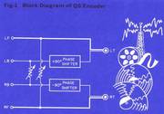
Fig-1 is a look inside the basic QS encoder which is available only in our professional type equipment, QSE-4. It actually consists of a matrix, a plus 90-degree phase shifter and a minus 90-degree phase shifter. The first phase shifter shifts the phase of the left-back signal by plus 90 degrees. The second shifter shifts the phase of the right- back signal by minus 90 degrees. Together, the entire circuit system works to encode the original four signals into just two. The system encodes all of the original signals and then makes it possible to position them correctly during just as they were in the original sound field ..... and of course in all 360-degree directions.
Basic QS Decoder
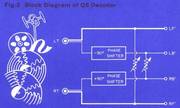
Fig-2 is the basic QS decorder, or rather, a block diagram of it. What it does is exactly the opposite of encoding ..... for it unscrables the left-total and right-total signals back into the original four signals.
.
90-degree Phase Shifters
Any matrix encoder that encodes four signals into two must encode the two rear (back) signals in reverse phase (i.e., 180 degees out of phase with each other). However, if we fed these two encoded signals to a decoder, the two rear speakers would be in reverse phase also, creating undersirable results.
.

- Fig-03

In order to avoid this reverse-phase problem at the time of decoding, Sansui has invented a new way to accomplish the 180-degree phase difference required during encoding. It is a pair of 90-degree phase shifters - one plus 90-degree phase shifter, and one minus 90-degree phase shifter. As Fig-3 illustrates, they work in the QS encoder to advance the phase of the left-back (LB) signal by 90 degrees from the left-front (LF) signal, while delaying that of the right-back (RB) signal by 90 degrees from the right-front (RF) signal. Then, in the decoder, they do exactly the opposite.
The marvelous consequence of this phase shifting is that the two rear speakers reproduce sound in phase again to create a most natural sound field. This is one of the most unique and advantageous features of the QS regular matrix system.
.
Movements of Stylus Tip
- Fig-04


- Fig-05

- Fig-06

- Fig-07

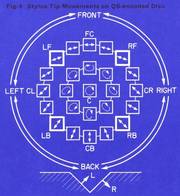
Now, let's take a look at how the encoded left-total and right-total signals are stored in a 2-channel stereo disc record. This is another way to better understand the QS regular matrix system. Fig. 4 shows how the reproducing stylus tip actually moves when it tracks a QS-encoded 4-channel disc record. As you can see from the different movements of the stylus tip, the QS regular matrix system does actually reproduce all the sounds in a complete 360-degree sound field. For comparison purposes, note the upper half of the circle, which represents the conventional 2-channel stereo record sound signals only.
.
Compatibility
To see the compatibility of the QS regualr matrix 4-channel system with regular 2-channel stereo playback, let's examine how 4-channel signals are positioned in 2-channel playback.
We saw in the preceding discussion of the stylus tip movements that the cutting system for QS 4-channel stereo is compatible with the cutting system for the conventional stereo disc. That is, you can play a QS-encoded 4-channel disc via an ordinary 2-channel stereo system for ordinary stereo reproduction. In this case, all 4-channel signals are perfectly reproduced, as you can see in Fig. 5. The signals which would be positioned in the back of the reproduced 4-channel sound field will then spread outside of the left and right stereo speakers. This creates a rich sense of stereo perspective, more so than the conventional stereo disc. It also adds a great sense of pressence.
Sound Pressure Response of Basic QS Decoder
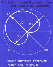
Now, let's return to the main theory of the QS regular matrix system with QS vario matrix circuit. Let us first suppose that a sound is generated at left front, and that the resultant signal is encoded through the QS encoder. If we used the basic QS decoder to reproduce that signal, part of the signal will leak out to the two adjacent channels. The sound pressure response diagram in Fig-6 shows this situation. In a matrix 4-channel system, the position of each signal is thus always established by the interrelationship of three speakers. This sound pressure response pattern is true for signals at all positions in the original 360-degree sound field.
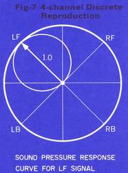
Fig-7 shows for comparison purpose, the sound pressure response pattern for the same left front signal as achived by discrete 4-channel tape recording.
QUESTION:
Could you explain about the new QS vario matrix in more detail? How it works, what it actually does and so forth?
ANSWER:
Yes. First of all, let me make the following points very clear.
.
- (1) The QS vario matrix circuit is a technique to improve the decoding effectiveness of the QS regular matrix system. It does not change the system itself, and the QS encoder remains unchanged.
- (2) When we say it improves the decoding effectiveness, we mean that it does away with the classic drawback of matrix 4-channel systems - i.e., insufficient inter-channel separation.
- (3) The QS vario matrix circuit reduces the interchannel crosstalk by automatically controlling the matrix parameter, but does not tamper with the amplitude gain in each channel at all. It is in this respect that it differs entirely from the so-called gain control logic decoders. What this means is that, if a separate, independent signal existed simultaneously in a channel where the crosstalk from the main channel if appearing, that signal would not be cancelled but would be reproduced in full.
- (4) For this reason, we believe the QS vario matrix to be a most effective decoding technique, totally retaining the musical qualities of the program source.
- (5) Thex cost of the QS vario matrix circuit is inexpensive. It is expected that it will be made into an integrated circuit (IC) in the near future; it will then cost less and become smaller in size.
.

- Fig-08


- Fig-09

- Fig-10

Now, then, let us turn to the actual working mechanism of the QS vario-matrix controls the operating parameter of the decorder matrix according to the input signals. Also, we've seen the sound pressure response curves of the basic QS decoder without the QS vario matrix and of discrete 4-channel tape reproduction as they reproduce a left front (LF) signal.
Actually, the controlling of the matrix parameter makes if possible to preset the sound pressure response curve for the same LF signal anywhere in the region indicated by the two dotted arrows on the lower illustration of Fig. 8.
This is effectively demonstrated on the upper illustration of the same figure. It assumes that an infinite number of speakers (though, in this actual illustration, only 16 are indicated for simplicity) are placed to form a circle around the listener. Then the amount of crosstalk (the volume of sound leakage) from the LF channel appearing in each spaker is indicated as the amount of solid color in each speaker. The outer circle shows this for the basic QS decoder without the QS vario matrix circuit, while the inner circle does the same for discrete 4-channel tape reproduction. What the QS vario matrix does is to control the matrix parameter and change the heart-shaped sound pressure response curve to the full circle of discrete reproduction. On the upper illustration, this means changing from the outer circle to the inner circle.
Fig. 9 shows the actual control of the sound pressure response curve. In this illustration, it is assumed that we want to reduce the 0.7 crosstalk of the LF signal appearing in the RF and LB channels to, say, 0.2.
We can do this by changing the matrix parameter instantaneously so that we derive the RF' and LB' signals from two points close to the RB' position where there is no crosstalk whatsoever from the LF signal. These two points, for instance, can be located where the two dotted lines join the circle shown in Fig-9. The function of the QS vario matrix circuit is to do this task automatically according to each input signal.
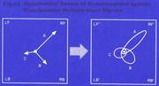
Fig. 10 shows the operation of QS vario matrix circuit against simultaneous multiple input signals.
Actually, the QS vario matrix operates in much the same manner. But if these multiple input signals were of different levels and directionalities - as the signals A, B, and C are in Fig. 10 - then the directionalities of the weaker signals - B and C - would be somewhat obscured ..... at least in terms of physical measurements.
.
(2) QS vario-matrix decoder
QUESTION:
It was said that the QS vario matrix is a technique to cancel the inter-channel crosstalk without altering the gain in each channel. This, I understand, is the theory of directional masking. What is directional masking?
ANSWER:
As stated in the preceding discussion pertaining to Fig. 10, when a number of signals enter the decorder simultaneously (which is the case in music), the QS vario matrix controls the matrix in such a way as to accentuate the directionality of the louder signal (and thereby create greater inter-channel separation). But in the process, it would somewhat obscure the directionalities of the weaker signals.
However, the human ear does not sense this obscuring of the directionalities of the weaker sign is.
This is because, when a number of sounds arrive at our ears simultaneously from different directions, our sense of hearing is momentarily fixed on the loudest of these sounds. And it is insensitive to the directions from which the weaker sounds come. In the terminology of psycho-acoustics, this phenomenon is called directional masking. Thus, to our ears, the 4-channel sound field reproduced by the QS vario matrix circuit sounds almost identical to the original, live, multi-dimensional sound field.
.
QUESTION:
Electonically, speaking, how is the QS vario matrix circuit constructed?
ANSWER:

- Fig-11

- Fig-12

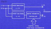
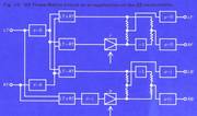
Fig. 11 shows a block diagram of teh QS vario matrix circuit. In terms of electronics, this circuit consists primarily of a phase discriminator, a apir of matrix parameter controllers, and two special-purpose processors.
You see, all of these components work together in a special way. But to study the circuit more closely, let's take a look at a close-up protion of the block diagram. Fig. 12 shows the front-channels portion. In it, the front sub signal is controlled in level through a variable gain amplifier in the matrix parameter controller, according to a control signal. The sub signal that is controlled then joins the main signal in the processor to create the separation between the LF-tick and RF-tick signals. It is the phase discriminator that produces the control signal from an interrelationship of the left-total and right-total signals.
(3) QS new Synthesizer
QUESTION:
I understand the QS vario-matrix circuitry synthesizes regular 2-channel recordings with startling effect. Coult you expalin why and how it is so?
ANSWER:
The availiability of 4-channel stereo sources is expanding rapidly, but is still rather limited both in qunatity and variety as compared to conventional stereo sources (records, tapes, etc.). It therefore is to the immense advantage of music fans to be able to transform these popular stereo sources into 4-channel sound. Today.
From the beginning, Sansui's QS 4-channel decoders and this 'synthesizing' capability. But now, with the invention of the QS vario matrix technique and the addition of a supplementary circuit called 2-4 Synthesizer Encoder, it is far more effective.
Actually, the new synthesizer offers two 4-channel effect - surround and hall.
.
- Surround: As the name suggests, the sound surrounds the listener to make him feel as if he were participating in the performance. This mode ideal for rock and pop music.
- Hall: Again as the name suggests, the acoustic effect of a concert hall is closely simulated in this mode, with the stage in front of the listener and the ambience around him. Many listeners prefer Hall for classic music, big band jazz and live recordings.
.
How does the QS Synthesizer work?
Fig. 13 shows the relationship between the standard 2-channel stereo perspective and a 4-channel sound field.
This diagram shows where the various positions of the line between the left and right stereo speakers are located in the "synthesizea" 4-channel sound field when a 2-channel stereo record is converted to 4-channel by the QS Synthesizer.
The upper curve represents the original 2-channel stereo perspective. The line below it shows the adjusted perspective ..... as expanded by the new 2-4 Synthesizer Encoder. As you can see, the entire line is stretched and bent to create a 4-channel sound field.
(4) QS vario-matrix for SQ?
QUESTION:
Why & how does the QS vario-matrix decode SQ records without infringing upon original SQ decoding technology?
ANSWER:
- Fig-14

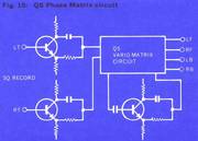
- Fig-15

- Fig-16

The diagrams in Figs. 14 and 15 show a phase matrix circuit as an application of the QS vario-matrix system. The four outputs through the Phase Matrix circuit are equivalent to the outputs through the basic SQ decoder. By varying the matrix control coefficients, the vector inter-relation will be improved, and the sound image in the corners of the sound field will have a separation factor of between 6dB and infinity.
In the basic SQ decoder, when there is a signal either in CF (center front) or CB (center back), there is no separation whatsoever between front and rear. But with Sansui's QS vario-matrix and its application as a Phase Matrix circuit, a great deal of separation is provided and the so-called "phantom image" appears very clearly as it should.
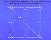
For example, when a signal exists at CF, the separation between CF and CB is infinite. When an image of the original sound field exists somewhere between LF and RF, front-back separation will be between 6dB and infinity. The same applies when an image exists at CB or somewhere between LB and RF. Separation between back and front will also be between 6dB and infinity. Fig. 16 shows the overall separation values.
The use of the QS vario-matrix circuit thus reproduces SQ-encoded sources faithfully as intended and with excellent separation. It also has the advantage of eliminating the undersired effects of relying solely on phase differences for LT-RT discrimination, and thus greatly improves the separation of the phantom image.
contact us
SANSUI ELECTRIC CO., LTD. 14-1, 2-CHOME, IZUMI, SUGINAMI-KU, TOKYO 168, JAPAN/TELEPHONE: 323-1111/TELEX: 232-2076
SANSUI ELECTRONICS CORPORATION 55-11 QUEENS BLVD. WOODSIDE, NEW YORK 11377, U.S.A./TELEX: NEW YORK 422633 SEC Ul
SANSUI AUDIO EUROPE S.A. DIACEM BUILDING, VESTLNGSTRAAT 53-55, 2000 ANTWERP, BELGIUM/TELEX: ANTWERP 33538
- Anmerkung : Ich glaube, da ist heute niemand mehr, um Ihre Fragen zu beantworten. Sparen Sie das Geld für gute Musik.
.